简体中文
简体中文 English
 繁体中文
繁体中文 Deutsch
PCB drilling solution
PCB drilling solution
1.1 Overview
For single-sided or double-sided PCB boards, non-plated through holes or plated through holes are drilled directly after cutting, while for multi-layer boards, drilling is performed after lamination. Traditionally, holes are classified not only by whether they are plated or not, but also by function: component holes, tooling holes, vias, blind holes, and buried holes (the latter two are also types of vias). With the recent trend of electronic products being 'light, thin, short, small, and fast', drilling technology has advanced rapidly, with mechanical drilling, laser drilling, and photo-defined holes being applied to different board levels. This article focuses on mechanical drilling using YSA Yisa spindles.
1.2 Process
Cutting, Drilling, Rounding, Edge Grinding, Burr Removal
Cutting refers to cutting the board into specific sizes according to order requirements; rounding involves processing the originally sharp corners into rounded corners for easier subsequent processing; edge grinding aims to polish the board edges to prevent cuts; burr removal removes burrs around the holes.
1.3 Hole Diameter Parameters
The minimum via hole generally accepted by customers is 0.3mm, and the maximum drill hole is 6.3mm. However, a 0.3mm via is not the limit of the drilling machine; the mechanical drilling limit is
0.15mm.
Due to production costs and process difficulty, it is recommended to avoid 0.1mm and 0.2mm holes in PCB design. Not only are drill bits prone to breakage, but the increased process difficulty and cost also lead to more defective boards. Therefore, it is suggested to design via holes at
≥0.35mm,
Extremely high requirements for YSA drilling spindles.
1.4 PIN
Process:
During drilling, except for drilling blind holes or when extremely high precision of board hole positioning is required using single-piece drilling, multi-piece drilling is typically used, meaning each stack consists of two or more boards. The number of boards per drill is determined by: 1. Board precision requirements, 2. Minimum hole diameter, 3. Total thickness, 4. Total copper layers. Since multiple boards are drilled together, each board is first fixed with pins before drilling, a process performed by a pinning machine. For double-sided boards, it is simple, mostly using edge alignment, with hole punching and pinning completed in one continuous action. Multilayer boards are more complex and require a dedicated pinning machine for multilayer boards.
1.5 Drilling tools and equipment
Drilling machine:
There are many types and configurations of drilling machines. The following list highlights key evaluation points.
A. Number of spindles: directly related to production output
B. Effective drilling board size
C. Drilling machine table: choose a material with low vibration, high strength, and good flatness.
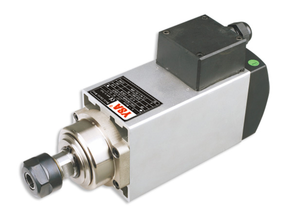
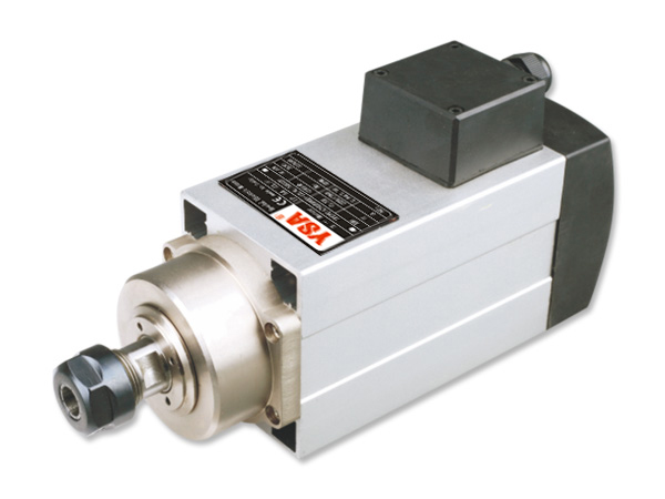
D. Spindle selection: YSA high-precision ER collet spindle
E. Drill disk: automatic drill bit change and bit count
F. Pressure foot
G. X, Y, and Z axis drive and dimensions: precision, independent X and Y movement
H. Dust collection system: works with pressure foot for good chip removal and drill cooling
I. Step drill capability
J. Broken Bit Detection
K. Run Out
Slot Drill:
Minimum slot drill is 0.65mm; slot holes are called connected holes. Compared to 'drill bits', slot drills are relatively less prone to breakage. However, when designing slot holes, do not make them smaller than 0.65mm.
1.6 Drilling Room Environment Design
A. Temperature and Humidity Control
B. Clean Environment
C. Floor Load Capacity
D. Insulation Grounding Considerations
E. External Vibration Interference
1.7 Material Introduction
Materials used in drilling operations include drill bits, backup boards, entry boards, etc. They are introduced one by one below: Figure 6.1 shows a schematic diagram of several materials used in drilling operations.
6.4.2.1 Drill Bit
Its quality has a direct and immediate impact on the drilling quality. The following will briefly describe its material, external structure, and management.
A. Drill Bit Material The drill bit is mainly composed of three materials:
a. Tungsten Carbide (WC) with high hardness and strong wear resistance
b. Impact-resistant and fairly hard cobalt
c. Organic adhesive.
After the three powders are uniformly mixed in proportion, they are sintered in a precisely controlled furnace at high temperature in a mold. The composition is about 94% tungsten carbide and about 6% cobalt. Wear resistance and hardness are key evaluation points for drill bits; finer alloy particles can improve hardness and are suitable for drilling small holes. Typically, the alloy particles are less than 1 micron.
B. External Structure
1. Shank
The part clamped by the spindle fixture; stainless steel is sometimes used to save material.
There are 4 shapes for the overall drill geometry:
(1) Straight Shank, where the drill portion is the same thickness as the handle,
(2) Common Shank, where the drill portion is thicker than the shank.
(3) Large-hole drill with a drill portion larger than the handle,
(4) Tapered drill for small holes.
C. Drill Inspection and Re-sharpening
a. Inspection method: 20-40x stereo microscope inspection
b. Drill Re-sharpening: For hole wall quality and drill life, re-sharpening management can be performed according to the table below. Generally, for a stack of three 4-layer boards (High), the drill life can reach 5000-6000 hits, and can be re-sharpened a total of three times. (Re-sharpening hit count table)
Summary:
Using YSA servo drilling spindles, for drilling accuracy requirements of 0.15mm, the actual measured hole position deviation is 0.05mm runout, and the inner hole is smooth and burr-free, offering significant precision advantages for PCB precision drilling.
Related products
© 2012-2026 Shenzhen Chuanneng Automation Co., Ltd. All Rights Reserved. 粤ICP备2026080421