The characteristics and operation steps of power head drilling
2022-11-21
1. The concept of drilling, drill bit and drilling characteristics
1. The concept of drilling
The surface of the inner hole is one of the main surfaces on the part. According to the different functions of the part in the mechanical product, the inner holes of different structures have different requirements for precision and surface quality. According to the relative connection between holes and other parts, it can be divided into matching holes and non-fitting holes; according to their geometric characteristics, they can be divided into through holes, blind holes, stepped holes, tapered holes, etc.; according to their different geometric shapes , can be divided into round holes, non-round holes, etc. Since the drilling process of the power head is the processing of the inner surface of the part, it is difficult to observe and control the processing process, and the processing difficulty is much greater than that of the open surface such as the outer circular surface. The hole processing process mainly has the following characteristics:
(1) Drilling tools are mostly fixed-size tools, such as drills, reamers, etc. The changes in shape and size caused by tool wear will directly affect the accuracy of the processed hole.
(2) Due to the limitation of the size of the processed hole, it is difficult to increase the cutting speed, which affects the processing productivity and the quality of the processed surface.
(3) The structure of the tool is limited by the diameter and length of the hole size, and the rigidity is poor.
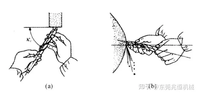
(4) During hole machining, the tool generally works in a semi-closed space, and it is difficult to remove chips; it is difficult for coolant to enter the processing area, and the heat dissipation conditions are not good. Power head drilling is a method of machining holes in solid materials with a drill. Bu on the drill press. Drilling, the workpiece is fixed, and the drill bit rotates (spindle motion is called main motion) while the shaft moves downward (called feed motion). Due to the structure of the drill bit of the power head, there are points such as poor rigidity and poor guiding, which affect the processing quality, and the drilling belongs to rough processing.
2. drill
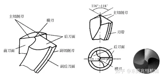
Tools for fitter drilling usually include drill presses and drill bits. Drilling machines commonly used by fitters for drilling include: bench drilling machines, straight drilling machines, radial drilling machines, etc. These devices have been introduced earlier, and will not be repeated here. The drill bit is the main cutting tool for drilling. It consists of a shank, a neck and a cutting part. The shank is the clamping part of the drill. It is used to connect with the machine tool and play the role of centering and power transmission. The drill shank has There are two kinds of taper shank and straight shank. Generally, the diameter is less than 13mm for straight shank, and the straight shank transmits small torque; the diameter is larger than 13mm for taper shank, and the taper shank can transmit larger torque. The neck is used for grinding the edge of the grinding wheel when grinding the drill bit. The specifications, materials and trademarks of the drill are generally engraved on the neck. The working part of the twist drill is divided into two parts: cutting and guiding. The working part is the main part of the drill bit. The front end is the cutting part, which undertakes the main cutting work. part. The material of the working part is generally made of high-speed steel, and the hardness after quenching can reach HRC62-68, and the material of the handle is generally 45 steel. The twist drill has two symmetrical spiral grooves, which are used to form cutting grooves, and are used for conveying cutting fluid and removing chips. The cutting part of the front end has two symmetrical main cutting edges, and the angle between the two edges is called the front angle, generally 116-118 degrees. The line of intersection of the two top surfaces is called the chisel edge. The two margins on the guide part play a guiding role during cutting, and the fork can reduce the friction between the drill bit and the hole wall of the workpiece. The cutting part of a standard twist drill consists of five edges (two main cutting edges, two minor cutting edges and a chisel edge) and six faces (two rake faces, two flank faces and two minor flanks) .
2. Drilling characteristics of power head
When drilling, the drill bit is cut in a semi-closed state, the speed is high, the cutting amount is large, and chip removal is difficult. Therefore, drilling has the following characteristics:
(1) The friction is relatively serious and requires a large drilling force;
(2) There is a lot of heat generated, but heat transfer and heat dissipation are difficult, so the cutting temperature is relatively high;
(3) The high-speed rotation of the drill bit and the resulting high cutting temperature can easily cause serious wear of the drill bit;
(4) Extrusion and friction during drilling are likely to cause cold hardening of the hole wall, making it difficult to process the next process;
(5) The drill bit is slender and has poor stability, which is prone to vibration and deviation during drilling;
(6) The machining accuracy is low.
3. Operation method and steps of power head drilling
Correctly mark the line on the surface of the workpiece and punch the sample punch. Before drilling, the sample punch in the center of the hole should be punched larger with the sample punch, so that the chisel edge of the drill bit falls into the cone pit of the sample punch in advance. When drilling, the drill bit is not easy to deviate from the center of the hole.
1. Selection of automatic drilling machine
There are many types of drilling machines, but they can generally be divided into desktop drilling machines, vertical drilling machines, and radial drilling machines. The desktop drilling machine is generally used to drill holes with a diameter of D<13mm on small workpieces. It uses a belt drive and a five-stage cone pulley for variable speed. Changing the different installation positions of the V-belt in the two cone pulley grooves can make the spindle obtain 5 kind of speed. Vertical drilling machine and radial drilling machine are mainly used to drill holes on larger workpieces. Generally, the maximum drilling diameter is 25, 35, 40, 50mm. The transmission of the vertical drilling machine is gear transmission. The drilling machine is equipped with positive and negative switches. When the drilling machine is in use, the speed must be stopped before changing speed. The speed can only be adjusted after the machine tool has stopped. Special attention is paid to it; fitters are strictly prohibited from wearing gloves when using the drilling machine, and female students must wear work caps.
2. Bit selection
The selection of twist drills is mainly based on two points, one is the diameter of the workpiece to be drilled, and the other is the material to be drilled.
3. Installation and disassembly of power head drilling bit
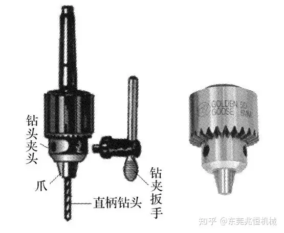
The straight shank drill bit can be inserted into the drill chuck and tightened with the drill chuck key. Do not hit the drill chuck to avoid damage to the chuck and the drill press. The taper shank drill bit should be installed only when it is consistent with the Morse taper hole of the drilling machine spindle. If the taper is inconsistent, the drill sleeve (taper sleeve) can be used; the taper drill can be removed by striking with an inclined iron, and the drill bit cannot be directly hit.
4. Correctly choose the clamping method of the drilling power head workpiece
Safety accidents in drilling are mostly caused by incorrect clamping methods of workpieces. Therefore, attention should be paid to the clamping of the workpiece. Due to the high cutting force during drilling, the workpiece must be clamped and cannot be loosened. The clamping is closely related to the shape of the workpiece. The clamping method of the workpiece when the fitter drills is as follows:
(1) For the drilling of small and thin plate parts, the workpiece can be placed on the positioning block, and theBench Viseclamping workpiece;
(2) For small and flat workpieces or medium parts, flat-nose pliers can be used to clamp. When clamping, the surface of the marked workpiece should be perpendicular to the drill bit; when the diameter of the drilling hole is more than 8mm, the flat-nose pliers must be fixed with bolts and pressure plates. ;
(3) For the workpiece that is drilled on the side of the cylindrical workpiece, V-shaped iron can be used to clamp the workpiece. When clamping, the axis of the drill bit should pass through the symmetrical plane of the V-shaped body vertically to ensure that the center line of the drilled hole passes through the axis of the workpiece Wire;
(4) For larger workpieces and other workpieces that are not suitable for clamping with vises, they can be directly fixed on the drilling machine table with pressure plate screws;
(5) For large workpieces, in addition to compression when drilling, jack support should also be used to prevent workpieces from being deformed by force;
(6) For the drilling of large quantities of workpieces, the drilling mold can be used for clamping and positioning.
5. Power head drilling
First select the speed appropriately, and check whether the drilling machine is running normally; then slowly cover the handle of the drill shaft, align the drill bit with the punch hole that has been drilled in advance, and prepare to pull out the drill; when pulling out the drill, wait for the drill bit to rotate stably before touching the workpiece On the surface, aim the drill bit at the center of the hole (sample punching hole) and try to drill a shallow pit about 1/4 of the hole diameter. At this time, observe whether the drilling position is correct, such as the drilled cone pit and the drawn drilling circle If you disagree, you should make corrections in time. The so-called borrowing means that if the drilled cone pit is less offset from the drawn drilling circumference, the workpiece can be moved (pull the workpiece to the opposite direction of the offset while pulling out the drill) or the main shaft of the drilling machine can be moved (rotating) When drilling with arm drilling machine) to correct; if there are many deviations, you can punch a few holes in the positive direction or chisel out a few grooves with an oil groove. When drilling, the feed force should not be too large, so as not to skew the drilling axis. The drill should be removed frequently to remove chips. When drilling a deep hole, if the drilling depth of the drill bit reaches 3 times the diameter, the drill bit will be withdrawn once for chip removal, and every time a certain depth is drilled, the drill bit will be withdrawn for chip removal once. Continuous drilling should be prevented, so that the chips are blocked in the spiral groove of the drill bit and the drill bit is broken. When the drilling is about to pass through, the feed rate must be reduced. If automatic feed is used, it should be changed to manual feed. During the drilling process, add enough cooling lubricating fluid to dissipate heat and cool the drill bit, reduce friction, improve the processing quality of the hole and prolong the service life of the drill bit. When the hole cannot be drilled, the stop limit of the drilling machine can be adjusted according to the required drilling depth. When the required hole depth is not high, the gauge limit can also be used. After the drill bit is blunt, it must be sharpened in time.
4. Precautions for power head drilling
In particular, it is required to:
(1) Before drilling, check whether the equipment is secure and whether the workpiece is firmly clamped;
(2) When installing the fixture on the workbench or directly installing the workpiece, the chips and dirt on the table must be wiped clean, otherwise the fixture or workpiece cannot be placed properly;
(3) When drilling, concentrate on the operation and wear protective glasses when drilling. In case drill cuttings leak out and hurt the eyes;
(4) It is not allowed to wear gloves to operate and use cotton yarn ends, and the cuffs must be tightly tied to prevent the drill bit from wrapping the gloves and hurting fingers; female students must wear work caps; do not directly support small or thin workpieces with hands, so as not to cause injury accidents .
(5) When drilling a through hole, iron should be lined under the workpiece to prevent damage to the workbench. When the hole is about to be drilled through, the feed force should be reduced as much as possible;
(6) When changing the speed of the spindle of the drilling machine, changing the drill bit and assembling and disassembling the workpiece, it must be done after stopping;
(7) To remove chips, use a brush instead of wiping or blowing with your mouth, and it must be done after parking;
(8) The head is not allowed to be too close to the main shaft of the rotating machine. When parking, the main shaft should be stopped naturally, and it is not allowed to brake by hand, nor can it be used for reverse braking.
5. Grinding method of standard twist drill